Introduction
Weld defects compromise structural integrity and can lead to catastrophic failures. Traditional manual inspection catches only 70-80% of defects and is slow, subjective, and expensive. Computer vision offers consistent, faster, and more accurate inspection.
This guide covers:
- Common weld defect types and how they appear visually
- Camera and lighting setup for weld inspection
- Traditional computer vision techniques with OpenCV
- Deep learning approaches for classification
- Production deployment considerations
Common Weld Defect Types
Understanding defect types is essential before building a detection system.
Surface Defects (Visible to cameras)
| Defect | Description | Visual Appearance |
|---|---|---|
| Porosity | Gas pockets trapped during solidification | Small dark spots or clusters |
| Undercut | Groove melted into base metal at weld toe | V-shaped shadow at weld edge |
| Overlap | Weld metal rolls over without fusing | Ridge or lip on weld surface |
| Spatter | Metal droplets on surface near weld | Scattered bright spots |
| Surface Cracks | Fractures on weld surface | Linear dark lines |
| Incomplete Fill | Insufficient weld metal | Depression or gap in weld bead |
| Burn Through | Excessive penetration | Holes or severe deformation |
Internal Defects (Require X-ray/ultrasonic)
| Defect | Description | Detection Method |
|---|---|---|
| Slag Inclusion | Non-metallic material trapped | Radiographic (X-ray) |
| Lack of Fusion | Incomplete bonding | Ultrasonic testing |
| Internal Porosity | Subsurface gas pockets | Radiographic |
| Root Cracks | Cracks at weld root | Ultrasonic/radiographic |
Note: This tutorial focuses on surface defects detectable with standard cameras. Internal defects require specialized imaging equipment.
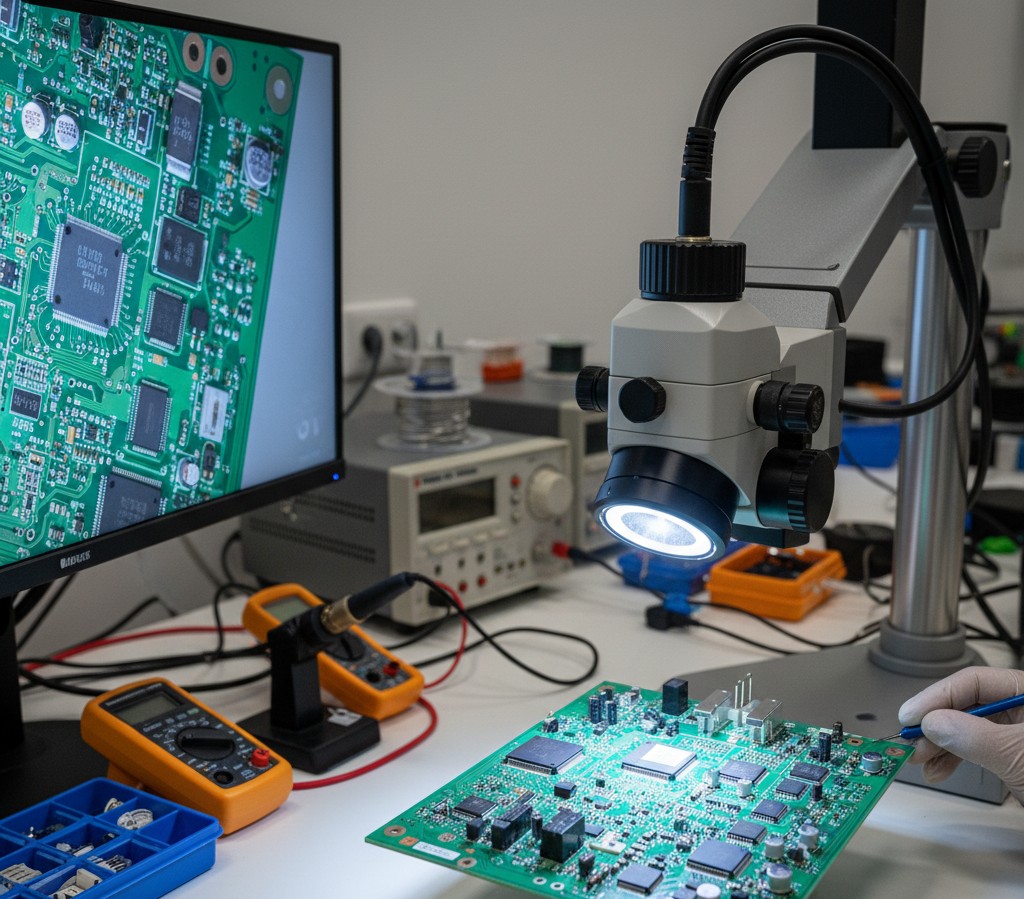
Imaging Setup for Weld Inspection
Good image quality is critical. Most detection failures stem from poor imaging, not algorithm limitations.
Camera Requirements
| Factor | Recommendation | Why |
|---|---|---|
| Resolution | 2-5 MP minimum | Capture small porosity (0.5mm+) |
| Sensor Type | Monochrome preferred | Better contrast, less data |
| Interface | GigE or USB 3.0 | Sufficient bandwidth |
| Frame Rate | 10+ fps for inline | Match line speed |
Lighting Approaches
Lighting matters more than camera selection for weld inspection.
1. Ring Light (Good for general inspection)
- Even illumination
- Reduces shadows
- Good starting point
2. Angled Directional Light (Best for surface defects)
- Creates shadows that highlight surface irregularities
- 30-45 degree angle from surface
- May need multiple angles
3. Structured Light (For 3D profiling)
- Projects pattern onto weld
- Captures height/depth information
- Detects undercut and incomplete fill
4. Dome Light (Diffuse illumination)
- Eliminates specular reflections from shiny welds
- Good for polished or stainless steel
Example Setup
1
2
3
4
5
6
Camera (overhead)
     |
     v
 [Weld Bead]  <-- Angled LED bar (45°)
     |
 Base Metal
Budget Setup (~£200-500):
For Raspberry Pi prototyping:
Traditional Computer Vision Approach
For well-controlled environments with consistent defect appearance, traditional CV methods work well.
Step 1: Image Preprocessing
1
2
3
4
5
6
7
8
9
10
11
12
13
14
15
16
17
import cv2
import numpy as np

def preprocess_weld_image(image_path):
    """Preprocess weld image for defect detection."""
    # Load image
    img = cv2.imread(image_path)
    gray = cv2.cvtColor(img, cv2.COLOR_BGR2GRAY)

    # Apply CLAHE for contrast enhancement
    clahe = cv2.createCLAHE(clipLimit=2.0, tileGridSize=(8, 8))
    enhanced = clahe.apply(gray)

    # Denoise while preserving edges
    denoised = cv2.bilateralFilter(enhanced, 9, 75, 75)

    return img, gray, denoised
Step 2: Weld Bead Segmentation
First, isolate the weld bead from the base metal.
1
2
3
4
5
6
7
8
9
10
11
12
13
14
15
16
17
18
19
20
21
22
23
24
25
26
def segment_weld_bead(gray_image):
    """Segment the weld bead region."""
    # Threshold to separate weld from base metal
    # Welds are typically brighter due to surface texture
    _, thresh = cv2.threshold(
        gray_image, 0, 255,
        cv2.THRESH_BINARY + cv2.THRESH_OTSU
    )

    # Morphological operations to clean up
    kernel = cv2.getStructuringElement(cv2.MORPH_ELLIPSE, (5, 5))
    cleaned = cv2.morphologyEx(thresh, cv2.MORPH_CLOSE, kernel)
    cleaned = cv2.morphologyEx(cleaned, cv2.MORPH_OPEN, kernel)

    # Find the largest contour (should be the weld bead)
    contours, _ = cv2.findContours(
        cleaned, cv2.RETR_EXTERNAL, cv2.CHAIN_APPROX_SIMPLE
    )

    if contours:
        weld_contour = max(contours, key=cv2.contourArea)
        mask = np.zeros_like(gray_image)
        cv2.drawContours(mask, [weld_contour], -1, 255, -1)
        return mask, weld_contour

    return None, None
Step 3: Porosity Detection
Porosity appears as small dark spots within the weld.
1
2
3
4
5
6
7
8
9
10
11
12
13
14
15
16
17
18
19
20
21
22
23
24
25
26
27
28
29
30
31
32
33
34
35
36
37
38
39
40
def detect_porosity(gray_image, weld_mask, min_area=10, max_area=500):
    """Detect porosity (dark spots) in weld region."""
    # Apply mask to focus on weld area
    weld_region = cv2.bitwise_and(gray_image, gray_image, mask=weld_mask)

    # Adaptive threshold to find dark spots
    thresh = cv2.adaptiveThreshold(
        weld_region, 255, cv2.ADAPTIVE_THRESH_GAUSSIAN_C,
        cv2.THRESH_BINARY_INV, 11, 2
    )

    # Remove noise
    kernel = cv2.getStructuringElement(cv2.MORPH_ELLIPSE, (3, 3))
    cleaned = cv2.morphologyEx(thresh, cv2.MORPH_OPEN, kernel)

    # Apply weld mask again
    cleaned = cv2.bitwise_and(cleaned, cleaned, mask=weld_mask)

    # Find porosity candidates
    contours, _ = cv2.findContours(
        cleaned, cv2.RETR_EXTERNAL, cv2.CHAIN_APPROX_SIMPLE
    )

    porosity_defects = []
    for contour in contours:
        area = cv2.contourArea(contour)
        if min_area < area < max_area:
            # Check circularity (porosity tends to be round)
            perimeter = cv2.arcLength(contour, True)
            if perimeter > 0:
                circularity = 4 * np.pi * area / (perimeter ** 2)
                if circularity > 0.5:  # Reasonably circular
                    porosity_defects.append({
                        'contour': contour,
                        'area': area,
                        'circularity': circularity,
                        'center': tuple(map(int, contour.mean(axis=0)[0]))
                    })

    return porosity_defects
Step 4: Crack Detection
Cracks appear as linear dark features.
1
2
3
4
5
6
7
8
9
10
11
12
13
14
15
16
17
18
19
20
21
22
23
24
25
26
27
28
29
30
31
32
33
def detect_cracks(gray_image, weld_mask, min_length=20):
    """Detect linear crack-like features."""
    # Apply mask
    weld_region = cv2.bitwise_and(gray_image, gray_image, mask=weld_mask)

    # Edge detection
    edges = cv2.Canny(weld_region, 50, 150)

    # Apply mask to edges
    edges = cv2.bitwise_and(edges, edges, mask=weld_mask)

    # Use Hough Line Transform to find linear features
    lines = cv2.HoughLinesP(
        edges,
        rho=1,
        theta=np.pi/180,
        threshold=30,
        minLineLength=min_length,
        maxLineGap=5
    )

    cracks = []
    if lines is not None:
        for line in lines:
            x1, y1, x2, y2 = line[0]
            length = np.sqrt((x2-x1)**2 + (y2-y1)**2)
            cracks.append({
                'start': (x1, y1),
                'end': (x2, y2),
                'length': length
            })

    return cracks
Step 5: Undercut Detection
Undercut appears at weld edges as a groove or shadow.
1
2
3
4
5
6
7
8
9
10
11
12
13
14
15
16
17
18
19
20
21
22
23
24
25
26
27
28
29
30
31
32
33
34
35
36
def detect_undercut(gray_image, weld_contour):
    """Detect undercut at weld edges."""
    # Create a region around the weld edge
    edge_mask = np.zeros_like(gray_image)
    cv2.drawContours(edge_mask, [weld_contour], -1, 255, 10)  # Thick edge

    # Inner region to subtract
    inner_mask = np.zeros_like(gray_image)
    cv2.drawContours(inner_mask, [weld_contour], -1, 255, -1)
    inner_eroded = cv2.erode(inner_mask, np.ones((15, 15), np.uint8))

    # Edge region only
    edge_region = cv2.bitwise_and(edge_mask, cv2.bitwise_not(inner_eroded))

    # Look for dark regions (undercut) along edge
    edge_pixels = cv2.bitwise_and(gray_image, gray_image, mask=edge_region)

    # Threshold for dark regions
    _, dark_regions = cv2.threshold(edge_pixels, 80, 255, cv2.THRESH_BINARY_INV)
    dark_regions = cv2.bitwise_and(dark_regions, dark_regions, mask=edge_region)

    # Find undercut regions
    contours, _ = cv2.findContours(
        dark_regions, cv2.RETR_EXTERNAL, cv2.CHAIN_APPROX_SIMPLE
    )

    undercuts = []
    for contour in contours:
        area = cv2.contourArea(contour)
        if area > 50:  # Minimum size threshold
            undercuts.append({
                'contour': contour,
                'area': area
            })

    return undercuts
Complete Detection Pipeline
1
2
3
4
5
6
7
8
9
10
11
12
13
14
15
16
17
18
19
20
21
22
23
24
25
26
27
28
29
30
31
32
33
34
35
36
37
38
39
40
41
42
43
44
45
46
47
48
49
50
def analyze_weld(image_path):
    """Complete weld defect analysis pipeline."""
    # Preprocess
    original, gray, processed = preprocess_weld_image(image_path)

    # Segment weld
    weld_mask, weld_contour = segment_weld_bead(processed)

    if weld_mask is None:
        return {'error': 'Could not segment weld bead'}

    # Detect defects
    results = {
        'porosity': detect_porosity(processed, weld_mask),
        'cracks': detect_cracks(processed, weld_mask),
        'undercut': detect_undercut(processed, weld_contour),
    }

    # Determine overall status
    total_defects = (
        len(results['porosity']) +
        len(results['cracks']) +
        len(results['undercut'])
    )

    results['status'] = 'FAIL' if total_defects > 0 else 'PASS'
    results['defect_count'] = total_defects

    return results


def visualize_defects(image_path, results):
    """Draw detected defects on image."""
    img = cv2.imread(image_path)

    # Draw porosity in red
    for defect in results.get('porosity', []):
        cv2.drawContours(img, [defect['contour']], -1, (0, 0, 255), 2)
        cv2.putText(img, 'Porosity', defect['center'],
                    cv2.FONT_HERSHEY_SIMPLEX, 0.5, (0, 0, 255), 1)

    # Draw cracks in yellow
    for crack in results.get('cracks', []):
        cv2.line(img, crack['start'], crack['end'], (0, 255, 255), 2)

    # Draw undercut in orange
    for defect in results.get('undercut', []):
        cv2.drawContours(img, [defect['contour']], -1, (0, 165, 255), 2)

    return img
Deep Learning Approach
For complex weld types or varied lighting conditions, deep learning outperforms traditional CV.
Dataset Requirements
You’ll need labeled images of weld defects. Options:
Public Datasets:
- DAGM Defect Dataset - Textured surface defects
- Severstal Steel Defect - Steel surface defects
- Custom collection from your production line (recommended)
Labeling:
- Minimum 100-200 images per defect class
- More data = better results
- Use Roboflow or CVAT for labeling
YOLO-Based Detection
YOLO models work well for real-time weld inspection.
1
2
3
4
5
6
7
8
9
10
11
12
13
from ultralytics import YOLO

# Train a custom model
model = YOLO('yolov8n.pt')  # Start with pretrained weights

# Train on your weld dataset
results = model.train(
    data='weld_defects.yaml',  # Your dataset config
    epochs=100,
    imgsz=640,
    batch=16,
    name='weld_detector'
)
Dataset config (weld_defects.yaml):
1
2
3
4
5
6
7
8
9
10
path: /path/to/dataset
train: images/train
val: images/val

names:
  0: porosity
  1: crack
  2: undercut
  3: spatter
  4: incomplete_fill
Inference
1
2
3
4
5
6
7
8
9
10
11
12
13
14
15
def detect_weld_defects_yolo(image_path, model_path='weld_detector/weights/best.pt'):
    """Detect weld defects using trained YOLO model."""
    model = YOLO(model_path)
    results = model(image_path)

    defects = []
    for result in results:
        for box in result.boxes:
            defects.append({
                'class': result.names[int(box.cls)],
                'confidence': float(box.conf),
                'bbox': box.xyxy[0].tolist()
            })

    return defects
Classification Approach
For pass/fail classification without localization:
1
2
3
4
5
6
7
8
9
10
11
12
13
14
15
16
17
18
19
20
21
22
23
24
25
26
27
28
29
30
31
32
33
34
35
36
37
38
import torch
import torchvision.transforms as transforms
from torchvision import models

class WeldClassifier:
    def __init__(self, model_path, num_classes=5):
        self.device = torch.device('cuda' if torch.cuda.is_available() else 'cpu')

        # Load model
        self.model = models.resnet50(weights=None)
        self.model.fc = torch.nn.Linear(self.model.fc.in_features, num_classes)
        self.model.load_state_dict(torch.load(model_path, map_location=self.device))
        self.model.to(self.device)
        self.model.eval()

        # Transforms
        self.transform = transforms.Compose([
            transforms.Resize((224, 224)),
            transforms.ToTensor(),
            transforms.Normalize([0.485, 0.456, 0.406], [0.229, 0.224, 0.225])
        ])

        self.classes = ['good', 'porosity', 'crack', 'undercut', 'spatter']

    def predict(self, image):
        """Classify weld image."""
        img_tensor = self.transform(image).unsqueeze(0).to(self.device)

        with torch.no_grad():
            outputs = self.model(img_tensor)
            probabilities = torch.nn.functional.softmax(outputs, dim=1)
            confidence, predicted = torch.max(probabilities, 1)

        return {
            'class': self.classes[predicted.item()],
            'confidence': confidence.item(),
            'all_probabilities': dict(zip(self.classes, probabilities[0].tolist()))
        }
Production Deployment
Edge Deployment Options
| Platform | Cost | Performance | Best For |
|---|---|---|---|
| Raspberry Pi 5 | ~£80 | 2-5 fps | Prototyping |
| Jetson Nano | ~£150 | 10-15 fps | Low-volume production |
| Jetson Orin Nano | ~£500 | 30+ fps | High-speed lines |
| Industrial PC | £1000+ | 50+ fps | Enterprise deployment |
System Architecture
1
2
3
4
5
Camera → Edge Device → Detection → PLC/Robot
                         ↓
                    Database
                         ↓
                   Dashboard
Handling False Positives
Weld inspection is sensitive to false positives. Strategies:
- Confidence thresholding - Only flag high-confidence detections
- Multi-frame confirmation - Require detection in 2+ consecutive frames
- Operator review queue - Flag borderline cases for human review
- Continuous model improvement - Log false positives, retrain regularly
Performance Benchmarks
Typical detection rates (varies significantly by application):
| Method | Accuracy | Speed | Training Data Needed |
|---|---|---|---|
| Traditional CV (tuned) | 85-92% | 50+ fps | None |
| YOLO (custom trained) | 92-98% | 20-40 fps | 500+ images |
| ResNet classifier | 90-96% | 100+ fps | 200+ images |
| Commercial systems | 95-99% | Varies | Vendor provided |
Common Pitfalls
- Poor lighting - 80% of failures are lighting issues
- Inconsistent imaging distance - Use fixed mounting
- Training on clean data only - Include real production variation
- Ignoring class imbalance - Defects are rare; use augmentation
- No baseline metrics - Measure manual inspection accuracy first
Recommended Resources
Hardware:
- Industrial USB 3.0 Cameras - For production deployment
- LED Ring Light - General illumination
- Structured Light Projector - For 3D profiling
For Raspberry Pi prototyping:
- Raspberry Pi 5 - Latest Pi for CV work
- Pi HQ Camera - Better optics for inspection
Some links above are affiliate links. We may earn a small commission if you purchase through them, at no extra cost to you. See our affiliate disclosure.
Next Steps
- Set up imaging - Camera + lighting in controlled environment
- Collect sample images - Good welds and various defect types
- Start with traditional CV - Faster to prototype
- Move to deep learning - When you have enough labeled data
Related tutorials:
Frequently Asked Questions
Can I detect internal weld defects with a camera?
No. Internal defects (subsurface porosity, lack of fusion, root cracks) require X-ray radiography or ultrasonic testing. This guide covers surface defects only.
What resolution camera do I need?
Depends on your smallest defect. Rule of thumb: defect should be at least 5-10 pixels across. For 0.5mm porosity at 100mm field of view, you need at least 1000 pixels across (1 MP minimum, 2+ MP recommended).
How much training data do I need for deep learning?
Minimum 100-200 images per defect class for reasonable results. More is better. 500+ images per class typically achieves production-quality accuracy.
Traditional CV or deep learning?
Start with traditional CV if:
- Controlled environment (consistent lighting, position)
- Well-defined defect appearance
- Limited training data
Use deep learning if:
- Variable conditions
- Complex or subtle defects
- You have sufficient labeled data